GD&T: The Basics of Geometric Dimensioning and Tolerancing
Dec 30, 2022
I. Introduction to GD&T
Definition of GD&T
Geometric Dimensioning and Tolerancing, or GD&T, is a system of symbols and techniques used to accurately communicate engineering and manufacturing tolerances on drawings and designs. It is a critical tool in the manufacturing industry, as it helps to ensure that parts and products are made to precise specifications and can function as intended.
But why is GD&T so important in manufacturing and design? Simply put, it allows for the accurate communication of tolerances and helps to eliminate misunderstandings and errors in the production process. Without a standardized system like GD&T, it would be much more difficult to ensure that parts and products are made to the correct dimensions and tolerances, leading to costly rework and delays.
In terms of GD&T symbols and terms, there are 14 primary symbols that are used to specify tolerances and dimensions on engineering drawings. These symbols include items like concentricity, circularity, and parallelism, among others. It's important to understand the meanings of these symbols and how to apply them correctly in order to accurately communicate tolerances in a drawing or design.
Overall, GD&T is a crucial tool in the manufacturing industry and is essential for ensuring that parts and products are made to precise specifications. By understanding the importance of GD&T and familiarizing oneself with the symbols and terms used, engineers and manufacturers can effectively communicate tolerances and help to eliminate misunderstandings and errors in the production process.
Why Use GD&T?
There are traditional methods for determining dimensions and tolerances. Why are geometric dimensioning and tolerances still necessary? Geometric dimensioning and tolerancing (GD&T) provide distinct advantages over conventional approaches. Let’s have a look at the advantages included.
Excellent Assembly
Using traditional dimensioning and tolerancing can create accurate individual components. However, a significant disadvantage of this method is that it does not ensure how effectively each part would interact when combined. Some parts cannot play a considerable role individually, yet they are necessary essential parts of a more oversized compartment that performs a specific function. If this part can not integrate well at the assembly level, it may alter the overall effectiveness of the component.
Consider the connecting rod as an example. It does not supply us with any advantage on its own. When attached to a piston and crankshaft, it will perform a beneficial function. In this case, it converts the linear motion of the piston into the rotational motion of the crankshaft. If you attach this assembly to a larger component, such as a generator or diesel engine, you will observe that it performs better, as these machines provide various purposes.
As a result, it is essential that our parts mate well with each other. This is why we require GD&T. Using it can ensure that our parts will fit properly and perform as intended.
Communicate Design Intent
The geometric tolerance symbols are easily understood. GD&T facilitates engineers’ ability to convey their thoughts to others in their sector. Its definitions, vocabulary, and rules are simple. As a result, it helps the designer in communicating his intent.
Saves Time and Money
If your design does not work effectively for its intended purpose, you may need to create a new one. You may need to repeat the cycle several times until you get a great part design that works for your component. This is not only a waste of your time but also of resources.
Utilizing GD&T can solve the cases mentioned above. GD&T helps in ensuring that you have a flawless design once and for all. Therefore, GD&T should be considered if you wish to reduce waste and get a lot done on time throughout your production process. Additionally, it facilitates your communication with others in the field. Consequently, it saves you time and effort.
What are the Guidelines of GD&T that Should be Considered?
Compared to traditional tolerances, geometric dimensioning and tolerancing is more powerful. However, this is only effective if all departments (design, engineering, production) are proficient in reading and interpreting information.
As a result, it is critical to adhere to the recommended guidelines while making engineering drawings to benefit everyone who will interact with the drawing at any stage of product development. The following guidelines are helpful to consider:
Clarity of the Drawing
The clarity of a drawing is even more essential than its accuracy and completeness. Some approaches for improving a drawing’s clarity include:
-
Draw true profiles for every part feature.
-
The direction of reading must be constant.
-
The reader must be able to read all dimensions when keeping the drawing upright.
-
Dimensions and tolerances should be labeled outside the drawing (not on top).
-
Utilize white space efficiently.
-
Briefly describe the part and its function.
-
Space out dimensions of parallel part features.
-
Specify angles only when they are not right angles (90°).
Tight Tolerances Only When Necessary
Tolerances must be maintained as loose as possible unless a part’s fit or function requires it. This decreases manufacturing costs as well as turnaround time. We propose allowing the machinists to choose the manufacturing method.
Additionally, the designer must provide a general tolerance for a drawing. This serves as the standard tolerance for all part features. For part features with varying tolerance limits, the designer must indicate them in the proper positions. When setting particular tolerance limits, prioritize functional characteristics above other characteristics.
How does GD&T Work?
GD&T works by specifying a design’s needed dimensions and tolerance value. Typically, a design’s tolerance value falls between the minimum and maximum limits. In other words, tolerance is the difference between the maximum and minimum limits.
The art of tolerancing entails specifying exactly the proper variations for every specified design feature to optimize the product approval rate within the limits of the manufacturing processes and following the part’s aesthetic and functional purpose.
We need GD&T symbols to properly ensure that the tolerance of the product does not go above or below the maximum and minimum tolerances. It is a symbol that helps in communicating the design intention and ensuring that the intended function is fulfilled.
GD&T Symbols
GD&T is feature-based, with each feature specified by different controls. Geometric tolerances are applied to features by feature control frames. GD&T symbols fall into five groups:
Form Control
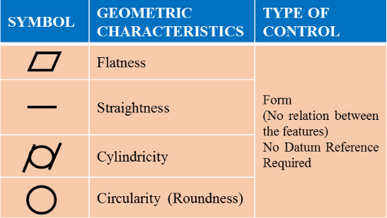
Form control specifies the shape of features, including:
Straightness: Straightness is classified as either line element straightness or axis straightness. The requirement for straightness describes how straight a target must be. It is used for lines instead of planes, indicating a curve in the center line or generatrix. As a result, straightness is employed to express the warpage tolerance of lengthy objects.
Flatness: The flatness criterion states how even a surface or perfectly flat a target plane should be. The most protruding and concave parts must be located at a certain distance between two vertically separated planes. Flatness is often measured between a surface’s highest and lowest points.
Cylindricity: Cylindricity is the degree to which a feature must resemble a perfect cylinder. It consists of straightness, roundness, and taper, making it costly to check.
Circularity or roundness: The roundness criterion describes how perfectly circular a target—the circular cross-section of a shaft, bore, or cone—must be. It also implies that the feature must be devoid of any characteristics or edges.
Orientation Control
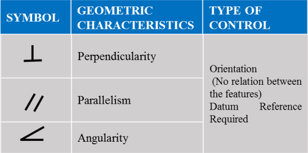
Orientation controls pertain to dimensions that change at angles, including:
Angularity: Angularity is defined as flatness at an angle to a datum. And it is also determined by two reference planes spaced the tolerance value apart.
Perpendicularity: Perpendicularity indicates flatness at 90° to a datum. It requires two ideal planes between which the feature plane must lie.
Parallelism: Parallelism denotes a parallel line at a specified distance. A cylindrical tolerance zone can be defined by inserting a diameter symbol in front of the tolerance value to define parallelism for axes.
Profile Control
Profile control describes the three-dimensional tolerance zone around a surface. It is further categorized into two, including:
Line Profile: A line profile compares a cross-section in two dimensions to an ideal shape. Unless otherwise indicated, the tolerance zone is defined by two offset curves.
Surface Profile: A surface profile is used to create two offset surfaces between which the feature surface must fall. Surface profile is a complicated control that is usually measured with a CMM.
Runout Control
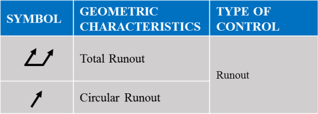
Runout control indicates the amount by which a specific feature can vary to the datums:
Circular Runout: Circular runout is employed when it is necessary to account for various errors, such as those present in ball-bearing mounted parts. During the inspection, the part is rotated on a spindle to measure the variance or ‘wobble’ around the rotational axis.
Total Runout: Total runout is measured at numerous surface points, describing the runout of a circular feature and a whole surface. This controls changes in straightness, profile, angularity, etc.
Location Control
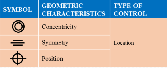
Location control uses linear dimensions to define feature locations:
Position: Position specifies the location of features to the other or the datums and is the most commonly used control.
Concentricity: The concentricity criterion specifies the concentricity’s accuracy of the axes of two cylinders (no deviation of the center). Concentricity compares the location of a feature axis to the datum axis.
Symmetry: The symmetry requirement specifies the accuracy with which a target is symmetrical to the datum (reference plane). This helps to guarantee that there are no irregularities in your design’s non-cylindrical sections. Symmetry is a complex control that is usually measured with a CMM.
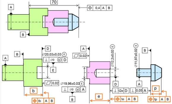
Feature Control Frame
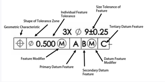
Simply said, the feature control frame controls the features of your design. Each feature control frame comprises a single message (requirement); if a feature requires two messages, two feature control frames are necessary.
A feature control frame’s first compartment contains one of the geometric characteristic symbols. A feature control frame may only include one of the symbols; if a feature has two needs, there must be two feature control frames or a composite tolerance. The symbol will specify the feature’s requirements, such as “this feature must be flat” or “this feature must be positioned.”
The second compartment of a feature control frame houses the feature’s total tolerance. If the diameter sign (⌀) appears before the tolerance, the tolerance denotes a diameter or cylindrically shaped zone. If there is no symbol before the tolerance, the default shape of the tolerance zone is parallel planes or a total broad zone, as in the location of a slot or surface profile. A material condition modifier, such as MMC or LMC, can be specified after the feature tolerance in the feature control frame if the feature has a size.
The third compartment provides datum feature references. However, not all designs necessitate the use of a datum feature. For instance, no datum feature reference is permitted if a form tolerance is specified, such as GD&T flatness or straightness. The datum feature references are often specified if a location tolerance such as position is specified.
Material Condition Modifiers
When describing geometric controls, it is frequently necessary to clarify that a tolerance applies to a feature at a specific feature size. An engineer can convey that intent using the Maximum Material Condition (MMC) and Least Material Condition (LMC).
The material condition modifiers are employed in the feature tolerance compartment of a feature control frame. When the features deviate from the stated condition, the MMC and LMC modifiers offer extra geometric tolerance beyond the set tolerance.
Maximum Material Condition (MMC): The condition in which the feature includes the maximum material within the specified size constraints.
Least Material Condition (LMC): The condition in which the feature includes the least material within the specified size constraints.
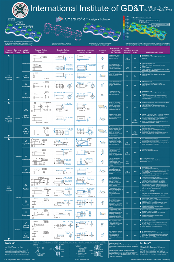
GD&T Symbols Chart
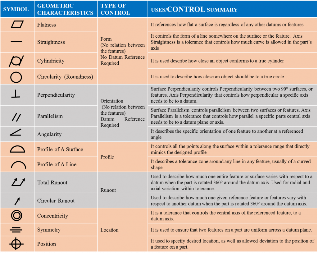
GD&T symbols are placed in the first compartment of a feature control frame and define the geometry characteristic of the feature that is to be controlled. The characteristics are grouped into four types of tolerance: form, orientation, location, and runout. The general primary control with a few notes is also shown. Below is a GD&T reference chart made by the International Institute of Geometric Dimensioning & Tolerancing:
Conclusion
In conclusion, Geometric Dimensioning and Tolerancing (GD&T) is a critical tool in the manufacturing industry, allowing for the accurate communication of tolerances and helping to eliminate misunderstandings and errors in the production process. We covered the importance of GD&T in manufacturing and design, as well as an overview of the symbols and terms used in the system. We also discussed the rules and best practices for using GD&T, as well as some advanced concepts such as composite tolerances and form tolerances. Finally, we looked at examples of how GD&T is used in practice and provided some tips for applying it in your own work.
If you're interested in learning more about GD&T, there are a number of resources available to help you get started. The ASME (American Society of Mechanical Engineers) offers a number of training courses and materials on GD&T, including the ASME Y14.5-2018 standard, which outlines the rules and symbols used in the system. There are also numerous books and online tutorials available that can help you learn more about GD&T and how to apply it in your work.
Overall, GD&T is a powerful tool for accurately communicating tolerances and ensuring that parts and products are made to precise specifications. By understanding the basics and continuing to learn more about the system, you can effectively use GD&T to improve the quality and efficiency of your work.