How to Control Surface Roughness of Parts in CNC Machining
Dec 12, 2022
How do you control surface roughness?
Surface roughness decreases with a decrease in feed rate(that is, the surface roughness is minimum when the feed rate is minimum). It increases with an increase in feed rate. The other turning parameters - cutting speed and depth of cut - have a less significant effect on surface roughness than the feed rate.
How can I improve my surface finish machining?
Four Tips to Improve As-machined Surface Quality
-
Increase Speeds, Reduce Feeds.
-
Minimize tool chatter and deflection.
-
Control chip removal.
-
Increase the rake angle.
What is surface roughness in machining?
Surface roughness is defined as the shorter frequency of real surfaces relative to the troughs. If you look at machined parts, you will notice that their surfaces embody a complex shape made of a series of peaks and troughs of varying heights, depths, and spacing.
What factors affect surface roughness?
Chip loadis the most influential factor that affects surface roughness since surface roughness deteriorates with the increase of chip load. However, due to dynamic behavior (low vibration), surface roughness decreases when high feed and depth of cut are used.
Why control of surface roughness is important in machining industry?
Rough surfaces generally wear more rapidly and have greater friction coefficients than smooth surfaces. Typically, roughness is a dependable predictor of mechanical part performance, as irregularities tend to form nucleation sites for breaks or corrosion. Conversely, roughness may encourage desired adhesion.
What’s the surface finish?
Surface finish, whose other term is the surface texture or surface topography, is a subjective term denoting a surface’s smoothness and general quality. It encompasses a surface’s tiny, local deviations from the flat ideal (a proper plane). In widespread usage, surface finish is often used as a synonym for surface roughness. Surface finish requirements are commonly found on technical drawings for mechanical parts, especially when pieces fit together closely, move against each other, or create a seal.
Surface finish is defined by four features: lay, waviness, flaws, and roughness. In machine shops, it is not unusual that surface finish is frequently used to indicate just surface roughness. Roughness is the most commonly defined characteristic of surface finish. However, before we go into the specifics of surface roughness, let’s first go through the four parts of surface finish.
This picture shows the relationship between lay, waviness, defects, and roughness:
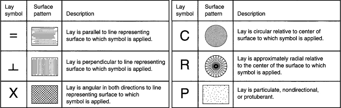
Lay
Lay is the predominant direction or pattern of the surface texture. It is determined by the manufacturing method used to create the surface, usually by the action of a cutting tool. The lay patterns could be parallel, perpendicular, radial, multi-directional, circular, crosshatched, or isotropic (non-directional). The chart below presents most of the possible lays a surface can take, together with the symbol used by a designer to specify them.
Waviness
Waviness refers to the most widely spaced surface finish deviations. These periodic surface flaws are greater than the roughness sample length yet tiny, brief, and regular enough not to be termed flatness faults. Warping from heating and cooling, as well as machining flaws from chatter or deflection, are common sources of surface waviness.
Over an assessment length, waviness is measured, and a waviness profile for that length is created. The waviness profile excludes any surface abnormalities caused by roughness, flatness, or shape changes. The peak-to-peak spacing of the waves is the waviness spacing (Wsm), whilst the wave height is defined by the average waviness (Wa) or total waviness (Wt) parameters. Waviness requirements are less prevalent than roughness requirements, although they might be significant for particular parts, such as bearing races or sealing surfaces.
Flaws
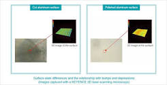
Flaws are random irregularities caused during the machining or production process, such as molding, drawing, forging, etc. Any scratches, cracks, holes, depressions, seams, tears, or inclusions can be called a flaw. Although some flaws relate to surface texture, they also affect surface integrity.
Surface Roughness
Surface roughness, often abbreviated as roughness, refers to the small, finely spaced deviations from the nominal surface that are determined by the material characteristics and the process that formed the surface. If these deviations are significant, the surface is rough; if they are small, the surface is smooth. In surface metrology, roughness is frequently conceived of as the high-frequency, short-wavelength part of a measured surface.
Surface roughness, often known as surface texture, is a computation of the relative roughness of a surface profile based on a single numeric parameter Ra. The arithmetic average of surface heights measured across a surface is known as Ra. A profilometer, or surface profile measuring instrument, can be used to detect surface roughness. It is essentially the average height of part roughness irregularities from a mean line.
Why is Surface Roughness Important?
Surface roughness is vital in defining how an actual thing will interact with its surroundings. It may have a significant impact on the performance and longevity of parts in many engineering applications. Rough surfaces wear faster and have higher friction coefficients than smooth surfaces. Surface roughness is a good predictor of mechanical part performance because imperfections provide nucleation sites for breakage or corrosion. Roughness, on the other hand, may promote desirable adherence. Surface roughness must be maintained at all times by engineers and manufacturers. It aids in the production of uniform procedures and trustworthy goods.
The surface finish may enhance surface electrical conductivities. It strengthens the product against wear while reducing friction, and it is essential for corrosion and chemical resistance. It also adds a particular aesthetic appeal to the items. It also assists in the adhesion of paints and varnishes. As a result, finishing methods have become the best way to get the right surface finish on different goods that have been machined or made.
How to Measure Surface Roughness?
Surface roughness may be measured using a variety of measurement techniques. Contact method, non-contact method, comparison method, and in-process method are all types of measurement techniques.
Contact Method
The contact method uses a stylus to assess the surface finish. The stylus is perpendicular to the surface while drawing along the surface. Roughness parameters are then determined using the registered profile produced by this procedure. The machining process must be disrupted in order to carry out this approach. On tested surfaces, a sharp stylus may leave micro-scratches.
Non-contact Method
Non-contact approaches employ light or sound. The stylus is replaced with optical instruments such as white light and confocal. These instruments use different measuring principles. Some non-contact equipment is constructed from contact-type detectors that have been reused by switching out the physical probe with microscopes and optical sensors.
The instrument will first deliver an ultrasonic pulse to the surface. The sound waves will then be altered and reflected back to the device. The reflected waves can then be evaluated to derive roughness parameters. Structured light, electrical capacitance, electron microscopy, interferometry, confocal microscopy, focus variation, atomic force microscopy, and photogrammetry are examples of non-contact methods.
Furthermore, light can evaluate surface roughness by projecting a laser beam onto the surface and measuring the intensity of the reflected light. The rougher the surface, the more light will be dispersed and the lower the intensity of the light that is reflected.
Comparison Method
The comparison method utilizes surface roughness samples obtained by the same equipment, process, and material as the studied surface. A sample is compared to a surface of known surface roughness by using the visual and tactile senses. This method is appropriate for non-critical applications due to the subjective nature of the procedure.
In-process Method
Inductance is an example of an in-process method. This technique makes use of magnetic materials to assess surface roughness. The inductance pickup measures the distance to the surface using electromagnetic energy. The parametric value obtained can then be used to assist in the determination of comparative roughness parameters.
The in-process method can provide continuous surface monitoring during machining or other operations, providing useful feedback to the operator. Furthermore, because they measure the surface under conditions that are closer to the real application, the in-process method may yield more accurate findings than other methods.
3 Categories of Surface Roughness Measurements Method
In terms of measuring surface roughness, there are three primary method categories: area, profiling, and microscopy techniques.
Area Techniques
Area techniques are used to measure the surface’s finite area. The measurement provides a statistical average of the surface’s peaks and troughs. Optical scattering, ultrasonic scattering, capacitance probes, and other methods are examples of these techniques. Area techniques are easier to automate and implement.
Profiling Techniques
Profiling techniques entail measuring the surface using a high-resolution probe. In this procedure, you should conceive of a phonograph needle in terms of sensitivity. A standard CNC probe might not be as effective.
Microscopy Techniques
Microscopy techniques rely on contrast measurements. The outcomes give useful information regarding surface peaks and troughs. Machinists may analyze surface finish in great detail using microscopy techniques, but this equipment is constrained by its tiny fields of view. Because electron microscopes work on a tiny scale, only a small piece of the surface can be observed at any given moment. Establishing average roughness parameters requires many scans.
Surface Roughness Chart Units And Abbreviations
The first time you view a surface roughness chart, you’re likely to notice a variety of units and abbreviations. The parameters are shown in units. However, other nations and organizations may use different measurements. Here are the four most often employed surface roughness symbols and parameters to be familiar with:
Ra-Roughness Average
Ra (roughness average), also called the centerline average, is the arithmetic average of all surface heights measured over a surface. It is one of the most commonly used parameters for measuring surface finish. Different surface roughness profiles, on the other hand, might have the same Ra yet behave differently. As a result, you may need to establish more surface roughness parameters to differentiate these discrepancies.
Rz-Average Maximum Height of Surface Profile
Rz is a measure of a surface profile’s average maximum height. This parameter is computed by taking the average of the five biggest discrepancies between peaks and valleys across the whole surface. It is possible for the Ra parameter to be insensitive to certain extremes, which can lead to faulty or imprecise results. Rz assists in removing some of these potential sources of error from the measuring process. Rz is the most commonly used international abbreviation.
RMS-Root Mean Square Roughness
RMS roughness is the root mean square of a surface’s peaks and valleys. The RMS roughness indicator is more accurate than Rz roughness since it employs more math and points on the surface. If you don’t want to calculate Ra, this is typically a decent solution.
To compute RMS, you will employ an algorithm that begins with the values and squares them. Next, the average of these squares will be taken, followed by the square root of the average. Rms employs a sine wave to determine the average curve, and the average deviation from the mean line may be observed.
Rmax-Vertical Distance between Peak and Valley
Rmax, which measures the vertical distances between a surface’s peaks and valleys, is great for detecting burrs, scratches, and other abnormalities that the Ra surface polish chart cannot detect. It may not be evident from the Ra surface finish chart. However, Rmax is quite sensitive to these anomalies. When identifying the maximum roughness of a surface, Rmax might be useful. You may then use various measuring methods to narrow it down further.
Which Surface Roughness Chart Unit Is Best?
Ra is the best surface finish measurement overall. It provides the most precise reading of the surface finish and is frequently seen on a surface finishing chart. While it might be helpful to focus on the extremes with Rmax and Rz, they are more specific.
Ra testing is standard practice at Metal Cutting, and it is what the majority of our clients request. Although Ra and RMS are occasionally used interchangeably since RMS = Ra x 1.11, we advise clients to use Ra. It is seen as more precise and is widely acknowledged throughout the business.
RMS occupies a middle ground since it is more accurate than Rmax and Rz. However, it is not as precise as Ra, who uses more sophisticated computation. If you don’t want to compute Ra, RMS might be a viable alternative.
Surface Roughness Conversion Chart
The machining surface roughness chart is useful for measuring standard surface roughness parameters. It is constantly used as a reference material by manufacturers to assure quality in the manufacturing process. The usage of the surface roughness conversion chart, on the other hand, is the most robust.
You may find surface roughness charts that compare the standard surface finishes for different metal cutting techniques, such as abrasive cutting, EDM, and surface grinding, as well as milling, turning, lapping, and polishing. Note that, when measuring surface finish, the lower the value, the smoother or less rough the surface.
The following Surface Roughness Conversion Chart compares several surface roughness scales in manufacturing processes. The table’s information is based on the premise that metal surfaces are being tested. Comparison values might vary by up to 25%. In the meantime, here are some abbreviations you’ll come across.
Ra = Roughness, average in micrometers & microinches
RMS = Root Mean Square in micro-inches
CLA = Center Line average in microinches
Rt = Roughness, total in microns
N = New ISO (Grade) Scale numbers
Cut-Off length = length required for the sample.
|
Surface Roughness Conversion Chart |
|||||||
|
Ra |
Ra |
RMS |
CLA |
Rt |
N |
Cut-Off |
|
|
micro-meters |
micro-inches |
(N) |
Length |
||||
|
in. |
mm |
||||||
|
0.025 |
1 |
1.1 |
1 |
0.3 |
1 |
0.003 |
0.08 |
|
0.05 |
2 |
2.2 |
2 |
0.5 |
2 |
0.01 |
0.25 |
|
0.1 |
4 |
4.4 |
4 |
0.8 |
3 |
0.01 |
0.25 |
|
0.2 |
8 |
8.8 |
8 |
1.2 |
4 |
0.01 |
0.25 |
|
0.4 |
16 |
17.6 |
16 |
2 |
5 |
0.01 |
0.25 |
|
0.8 |
32 |
35.6 |
32 |
4 |
6 |
0.03 |
0.8 |
|
1.6 |
63 |
69.3 |
63 |
8 |
7 |
0.03 |
0.8 |
|
3.2 |
125 |
137.5 |
125 |
13 |
8 |
0.1 |
2.5 |
|
6.3 |
250 |
275 |
250 |
25 |
9 |
0.1 |
2.5 |
|
12.5 |
500 |
550 |
500 |
50 |
10 |
0.1 |
2.5 |
|
25 |
1000 |
1100 |
1000 |
100 |
11 |
0.3 |
8 |
|
50 |
2000 |
2200 |
2000 |
200 |
12 |
0.3 |
8 |
Typically, surface finish is measured in micrometers or microinches; the smaller the value, the finer the surface polish. To put a few figures into perspective:
-
If the micrometers rating of your part is 12.5, the microinches rating is 500. This indicates that the surface of the part is rough and low-grade, most likely due to coarse feeds and heavy cuts.
-
If the micrometers rating of your part is 3.2, the microinches rating is 125. This is the roughest surface suggested for parts, and it is typically applied to those that must tolerate extreme stress, loads, or vibration.
-
If the micrometers rating of your part is 0.8, the microinches rating is 32. This is a high-quality machining surface finish that demands tightly controlled conditions but is very simple to create with cylindrical, centerless, or surface grinders. A suitable surface finish for parts that will not be subjected to continuous motion or severe loads.
Surface Finish Cheat Sheet
|
Micrometers Rating |
Microinches Rating |
Applications |
|
25 |
100 |
Rough, low-grade surfaces that result from saw cutting or rough forging. Therefore, such surfaces are suitable for certain unmachined clearance areas. |
|
12.5 |
500 |
These are rough, low-grade surfaces resulting from coarse feeds and heavy cuts. While the cuts come from turning, milling, disc grinding, and more. |
|
6.3 |
250 |
This type of surface finish results from surface grinds, disc grinds, milling, drilling, and more. Therefore, they are for clearance surfaces with stress requirements and design permits |
|
3.2 |
125 |
The roughest kind of surface is often recommended for parts. It is also used for parts subject to vibrations, loads, and high stress. |
|
1.6 |
63 |
Good machine roughness/finish with its production under controlled conditions. It also involves fine feeds and relatively high speeds. |
|
0.8 |
32 |
A high-grade machine finish, which needs close control. It is relatively easy to produce with cylindrical, centerless, or surface grinders. It is also preferred for products that do not require continuous motion or large loads. |
|
0.4 |
16 |
High-quality surface are often produced using emery buffing, lapping, or coarse honing. These finishes are therefore great options where smoothness is of high importance. |
|
0.2 |
8 |
Fine, high-quality surface finish produced by lapping, buffing, or honing. Machinists use this where rings and packings have to slide across the surface grain. |
|
0.1 |
4 |
A refined surface that is offered using lapping, buffing, or honing. Manufacturers use it only when there are mandatory design requirements. Therefore, it is the best finish in gauge and instrument works. |
|
0.05 |
2 |
Most refined surface finish produced with the finest buffing, honing, or superfinishing. Thus, they are best used for fine and sensitive precision gauge blocks. |
|
0.025 |
1 |
What is the Average Surface Roughness Value of Different Machining Processes?
When deciding how to make your metal products, there are a lot of things to think about. The chart below provides the average surface roughness values generated by common machining methods. But please note, many things affect how well a machining operation can make a certain surface roughness. Surface roughness values can be obtained under special conditions for each process.
|
Machining Processes |
Roughness Average Range |
|||||
|
Min. |
Max. |
Min. |
Max. |
Min. |
Max. |
|
|
RA(μm) |
RA(μm) |
RMS(μm) |
RMS(μm) |
CLA(μin) |
CLA(μin) |
|
|
Flame Cutting |
12.5 |
25 |
13.75 |
27.5 |
500 |
1000 |
|
Snagging |
6.3 |
25 |
6.93 |
27.5 |
250 |
1000 |
|
Sawing |
1.6 |
25 |
1.76 |
27.5 |
63 |
1000 |
|
Planing, Shaping |
1.6 |
12.5 |
1.76 |
13.75 |
63 |
500 |
|
Drilling |
1.6 |
6.3 |
1.76 |
6.93 |
63 |
250 |
|
Chemical Milling |
1.6 |
6.3 |
1.76 |
6.93 |
63 |
250 |
|
EDM Machining |
0.1 |
0.4 |
0.11 |
0.44 |
63 |
250 |
|
Milling |
0.8 |
6.3 |
0.88 |
6.93 |
32 |
250 |
|
Broaching |
0.8 |
3.2 |
0.88 |
3.52 |
32 |
125 |
|
Reaming |
0.8 |
3.2 |
0.88 |
3.52 |
32 |
125 |
|
Electron Beam |
0.8 |
6.3 |
0.88 |
6.93 |
32 |
250 |
|
Laser |
0.8 |
6.3 |
0.88 |
6.93 |
32 |
250 |
|
Electro-Chemical |
0.2 |
3.2 |
0.22 |
3.52 |
8 |
125 |
|
Boring, Turning |
0.4 |
6.3 |
0.44 |
6.93 |
16 |
250 |
|
Barrel Finishing |
0.2 |
0.8 |
0.22 |
0.88 |
8 |
32 |
|
Electrolytic Grinding |
0.2 |
0.6 |
0.22 |
0.66 |
8 |
24 |
|
Roller Burnishing |
0.2 |
0.4 |
0.22 |
0.44 |
8 |
16 |
|
Grinding |
0.1 |
1.6 |
0.11 |
1.76 |
4 |
64 |
|
Honing |
0.1 |
0.8 |
0.11 |
0.88 |
4 |
32 |
|
Electro-Polish |
0.1 |
0.8 |
0.11 |
0.88 |
4 |
32 |
|
Polishing |
0.1 |
0.4 |
0.11 |
0.44 |
4 |
16 |
|
Lapping |
0.05 |
0.4 |
0.055 |
0.44 |
2 |
16 |
|
Super Finishing |
0.025 |
0.2 |
0.0275 |
0.22 |
1 |
8 |
|
Sand Casting |
12.5 |
25 |
13.75 |
27.5 |
500 |
1000 |
|
Hot Rolling |
12.5 |
25 |
13.75 |
27.5 |
500 |
1000 |
|
Forging |
3.2 |
12.5 |
3.52 |
13.75 |
125 |
500 |
|
Perm. Mold Casting |
1.6 |
3.2 |
1.76 |
3.52 |
64 |
125 |
|
Investment Casting |
1.6 |
3.2 |
1.76 |
3.52 |
64 |
125 |
|
Extruding |
0.8 |
3.2 |
0.88 |
3.52 |
32 |
125 |
|
Cold Rolling, Drawing |
0.8 |
3.2 |
0.88 |
3.52 |
32 |
125 |
|
Die Casting |
0.8 |
1.6 |
0.88 |
1.76 |
32 |
64 |
|
μm=0.000001m=0.001mm |
||||||
|
μin=0.000001 in= 0.0254μ = 0.000025mm |
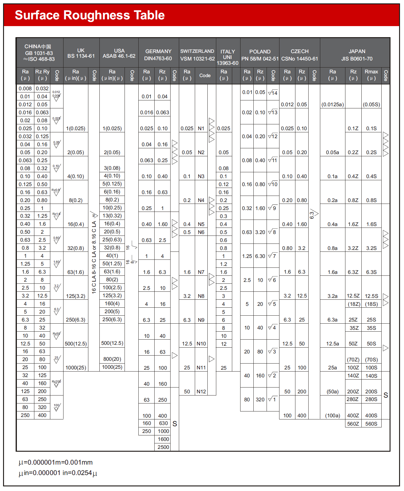
Surface Roughness Standard in Different Countries
Conclusion
In general, the failure of an engineered part begins at its surface as a result of an individual manufacturing-related fault or a progressive decline in surface quality. Finishing procedures are widely accepted as the best way to get the right surface finish on a wide range of machined and fabricated parts.
Surface finish is heavily reliant on the manufacturing process, and exceptionally smooth surface finishes typically need further processing, such as grinding or polishing. Because more processing would incur greater costs, the engineer or designer must avoid imposing unduly low roughness requirements. The roughness requirements should, wherever feasible, be within the constraints of the primary manufacturing process.
Due to the high cost and difficulty of achieving exact surface roughness in modern production, surface finishing processes demand the most effective approach to achieve the appropriate finishes on manufactured parts. From part design through post-processing and surface finishing, the SEANC team of engineers is prepared to assist you in achieving the best outcomes possible for your product. Our services are of the finest quality, and you can rely on receiving the best services on demand. Contact us immediately through email; we are always available to work with you.